UML State Machine Diagrams
When developing a product or programming software, UML state machine diagrams help to represent the lifecycle of individual objects in a clear and visual way. Although the diagram only comprises a few elements, it can be a key contribution to the success of the end product when used correctly. Learn why and in which cases it can make sense to use this kind of diagram and how you can create your own UML state machine diagram in the sections below.
What is a state machine diagram?
A UML state machine diagram (also known as a state diagram) visualizes the states of a finite automaton, i.e. a behavioral model comprising actions and states or state transitions. The diagram provides for an initial and final state and at least one intermediary state for each object within the model. The state machine diagram is, therefore, able to map the complete lifecycle of a system or subsystem or individual components and classes, regardless of whether these processes concern a coffee machine, an e-book reader or a technical component in a car, for example.
The state machine diagram is one of 14 types of diagrams of the Unified Modeling Language (UML) and the Systems Model Language (SysML). It’s based on a concept by David Harel, published in the scientific paper “Statecharts: A Visual Formalism for Complex Systems” in 1987. Other UML diagram types include the application case diagram and the component diagram.
What are the applications of UML state machine diagrams?
As mentioned above, state machine diagrams aim to describe the behavior of a system as precisely as possible. Among other things, the visualization of individual processes is designed to answer the following questions:
- What happens when the object is in a specific state?
- What state has to occur for a change in its behavior?
- What are the triggering actions?
- Which properties does the object need to have to switch state?
UML state machine diagrams are used wherever it makes sense to visualize states and transition conditions for an optimized development process. They are especially popular for designing embedded systems, for example, since these systems handle various automated signals and processes in the background which need to be optimally coordinated. In this case, a state machine diagram supports developers by visualizing all relevant control and regulatory functions, making them obvious at a glance.
The benefits of state machine diagrams can be illustrated using the example of the washing machine function “Aqua Stop”. The function regulates the interruption of water supply to a washing machine. It can be understood as its own system as part of a UML state machine diagram. Here, the graphical representation shows in which state and under which conditions the “Aqua Stop” function takes effect.
In various industry sectors like medical technology or transportation, state machine diagrams are used to explain complex situations. State machine diagrams are also applied in product and project management and engineering.
State machine diagram: overview of structure and components
Although UML state machine diagrams are based on just a few elements, the effective combination of these components allows complex sequences of states to be mapped. But what are the most important components and what does the fundamental structure of a state machine diagram look like?
States
If we consider the state machine diagram example for visualizing the states of a door, the following condition always needs to be met:
- The object is always in one of the two states: The door is either open or closed, but never simultaneously open and closed.
In more complex state machine diagrams, the rectangle can be divided into three sections representing behavioral specifications (see “Transition”).
Transition: how does a state change?
To switch from one state to the next, an action has to be triggered which represents a transition. This transition connects the states – visually depicted by an arrow. Conditions can apply for triggering such a transition. In principle, a distinction is made between internal and external transitions in UML state machine diagrams. While external transitions are mandatory when creating a state machine diagram, internal transitions don’t necessarily have to be included in the diagram.
In the state machine diagram for an elevator, for example, the condition for the action “close elevator door” could be that it had to be open for at least five seconds previously before switching state from “closed” to “open”.
External transition: state changes
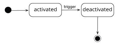
In the following example of a UML state machine diagram, for example, the transitions are known as external transitions. The transition, therefore, results in the object changing to a different state (entry/exit).
Example: If the alarm of a radio alarm clock is triggered, the state changes from “alarm activated” to “alarm deactivated”. The state changes.
Internal transition: state remains unchanged
In the case of an internal transition, an activity rather than a state change is triggered.
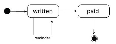
Example: In an accounting system, the automatic sending of an invoice can be triggered for an outstanding invoice (external transition). If a reminder is sent in response to an outstanding invoice, the dispatch of the reminder is considered an internal transition. Although the activity “send reminder” occurs, the invoice continues to be in the state “unpaid” until settlement.
Actions: why do states change?
Actions can describe in greater detail under which conditions a state is left to switch to the new state. When transitioning from the initial state to the first real state, this isn’t necessary; further action information is optional. If no action is specified, this means that it occurs automatically as soon as all activities in the previous states have been completed.
A NONE action (trigger / ANY trigger) means that the action is always occurring. Actions can be stated as a behavioral specification within the state or within the state transition (see “Transition”).
A triggering action must fulfill the following three conditions:
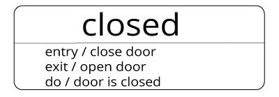
- entry: The action is automatically triggered when a state is entered, i.e. in all incoming transitions.
- exit: The action is triggered when leaving a state, i.e. in all outgoing transitions.
- do: The action is repeatedly triggered when the state isn’t changed.
These behavioral specifications can be noted within the state to simply show in which behavioral patterns the state changes. There are two ways to visually represent these triggers. First of all, they can be listed within the corresponding state as demonstrated in the state machine diagram example below:
Pseudo States
If control elements influence the sequence of a state automation but do not possess any value parameters, these are called pseudo states. UML 2, the current version of the Unified Modeling Language, offers ten such pseudo states:
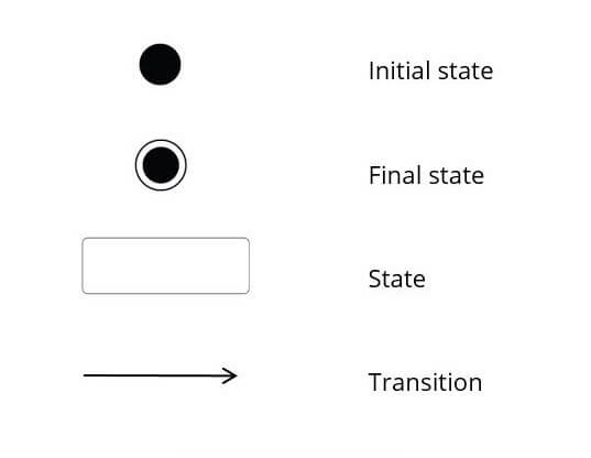
- Initial state: no incoming transitions and exactly one outgoing transition revealed by the starting state
- Final state: no outgoing transition and the end of the sequence
- Fork: split into multiple parallel states
- Join: merger of multiple parallel states
- Junction: hub for the connection of multiple transitions
- Choice: node from which multiple alternative transitions can be started based on the decision taken
- Entry point: summary of homogenous transitions that enter a composite state
- Exit point: summary of homogenous transitions that leave a composite state
- Shallow history: archive of the last active sub-state of a composite state
- Deep history: archive of the last active sub-state of all hierarchy levels of a composite state
Special: subordinate diagram
Depending on the complexity, sub-states are possible that provide a more detailed picture of the object state and possible behavioral patterns. These complex explanations in UML state machine diagrams are particularly common in technical contexts.
- Composite state: Here, a state can be defined in greater depth.
Example: A door can be in the state “open” or “closed”. Sub-states of the state “closed” could be “unlocked” and “locked”.
- Sub-machine state: Here a subordinate state machine diagram is added to a state. Sub-states that comprise multiple sub-states are known as complex states. The various sub-states can be run independently of each other, although they stand in relation to one another.
Example: In the case of a smartphone, the alarm function is just one of many features that can be associated with multiple states. If multiple alarms are programmed for different days of the week and times, they concern sub-states that run independently of each other.
Creating state machine diagrams: a simple example
A UML state machine diagram can be applied to a range of different objects. The example below shows the various elements by visualizing the states of an invoice. The most important elements of a UML state machine diagram are depicted as follows:
After the initial state as a pseudo state, the invoice occupies the state “written”. Ideally, the process should transition to the state “paid”. This transition can be described in greater detail by adding the action name “send”.
Once the invoice is paid, the invoice enters the state “paid”. Before this state is reached, it may be necessary to send a “reminder”. Since the invoice doesn’t change state in this case, this represents an activity or an internal transition. If the invoice is not settled, up to three reminders are sent.


